Summary:
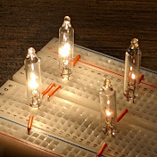
This video demonstrates a voltage doubler that uses two LEDs as rectifiers. It also shows the individual capacitor voltages measured with differential oscilloscope inputs.
Why This Matters:
Voltage doublers appear in many low-power supply stages where simple level shifting is required. Understanding the charging paths and ripple behavior helps engineers evaluate practical performance under different excitation frequencies.
Content covered in the video:
• Circuit layout using two LEDs, two 3,300-µF capacitors, a 100-ohm series resistor, and a 1-kΩ load
• Differential measurement of each capacitor using the Analog Discovery instrument
• Half-wave charging behavior for the upper and lower capacitors
• Summation of capacitor voltages to form the doubled output waveform
• Comparison between input frequency and output ripple magnitude
• Ripple reduction observed when the drive frequency increases from 1 Hz to 100 Hz
Download
0 formats
No download links available.
Visualize Voltage Doubler Operation using LEDs and Advanced Oscilloscope Techniques | NatokHD